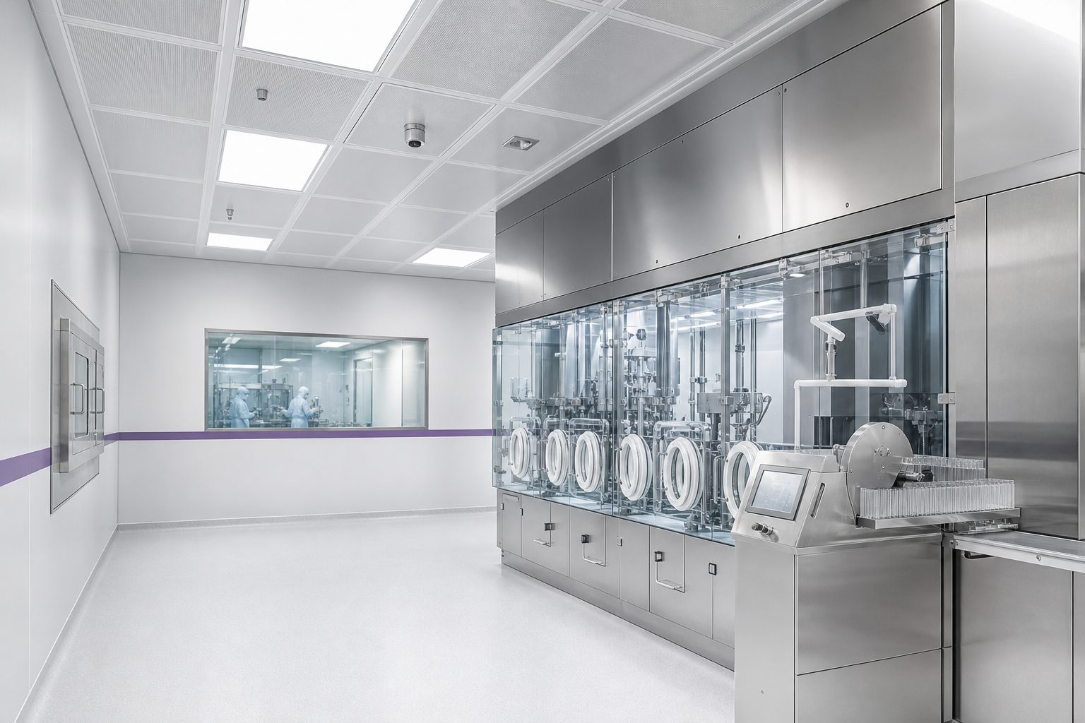
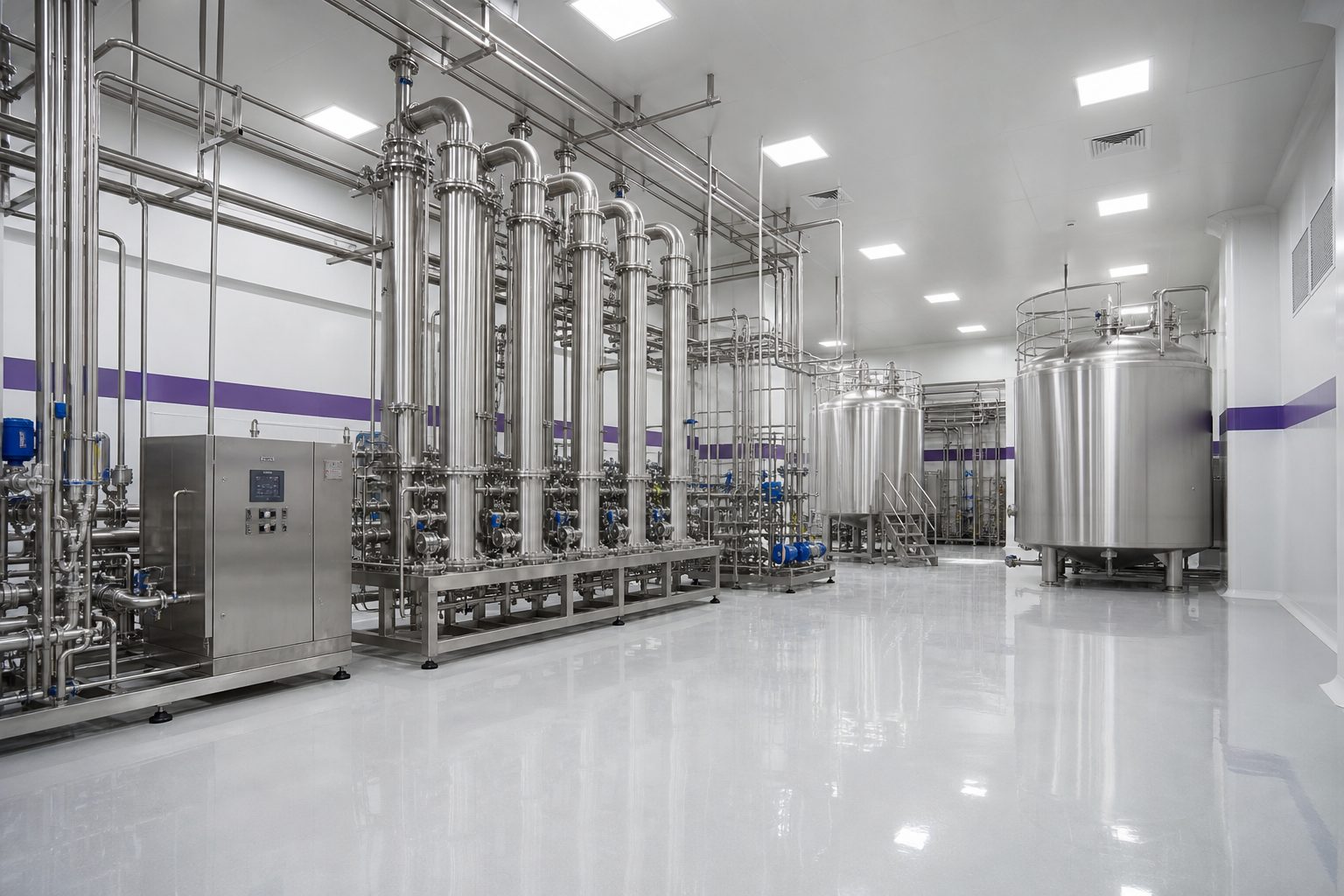
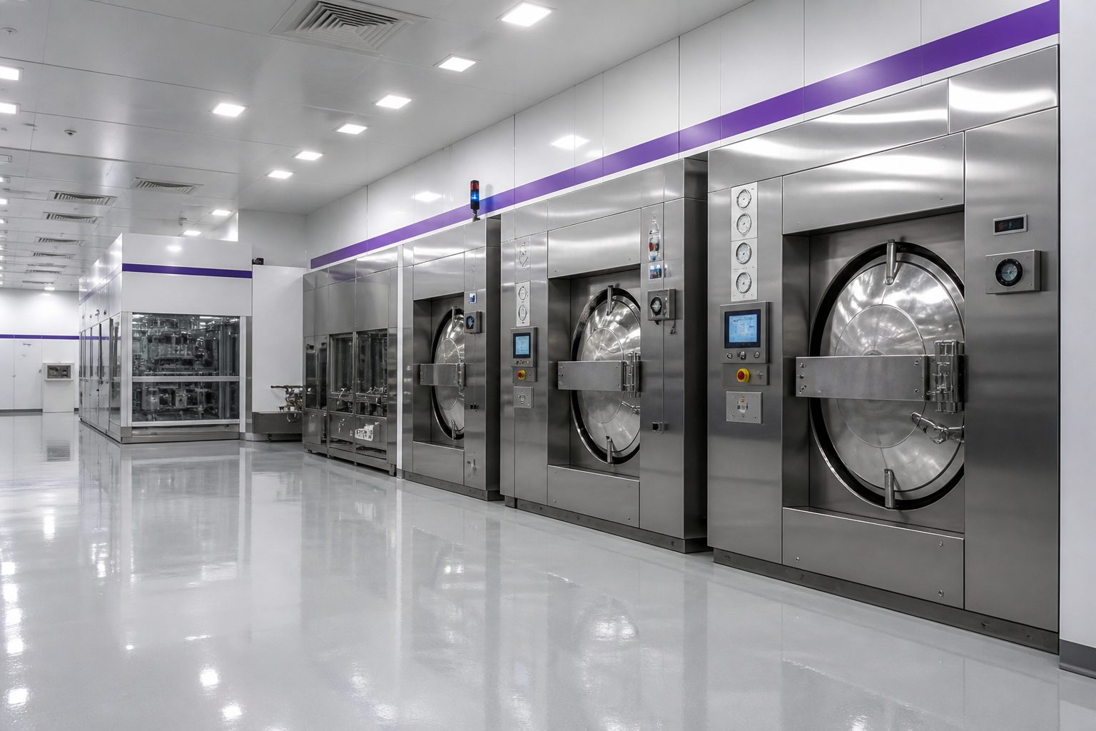
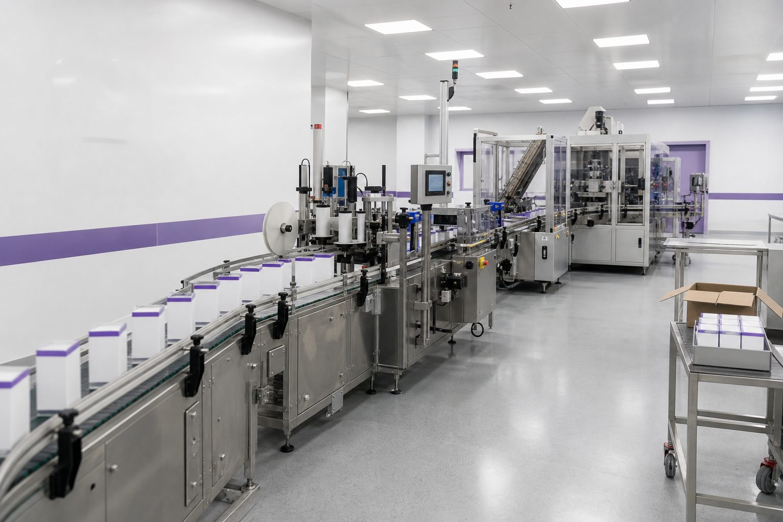
1. Modular Cleanroom Systems
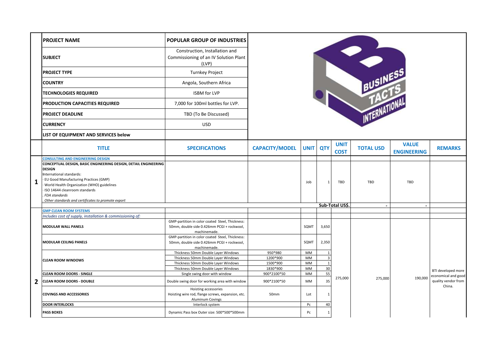
3,650 m² wall panels (50mm PCGI + rock wool), 2,350 m² walkable ceiling, doors, windows |
$275,000 |
$190,000 |
-$85,000 |
Direct OEM modular panel factory supply; optimized 50mm PCGI + rock wool envelope. |
2. HVAC High & Low Side
Double-skin AHUs, condensing units, GI ducting (TDC/TDF), 145 HEPA housings, 355 diffusers |
$249,750 |
$175,000 |
-$74,750 |
Direct component procurement and regional ducting fabrication; optimized air balance. |
3. Water Generation & Storage (WFI/PW)
LD2000/5 Water Distiller (2,000 L/h), 10,000L SS316L WFI storage tank, 50TR cooling tower |
$175,000 |
$140,000 |
-$35,000 |
Direct Chinese OEM skid fabrication with Siemens PLC controls and orbital welded loop. |
4. Factory Steam & Clean Utilities
2,000 kg/h dual-fuel boiler, 100 kg/h pure steam generator, oil-free screw compressor |
$165,000 |
$130,000 |
-$35,000 |
Skid-mounted pre-commissioned boiler and pure steam package direct from specialized OEM. |
5. Electrical Balance of Plant
Main LV/HT switchgear, distribution panels, UPS backup, cleanroom lighting, cable trays |
$440,000 |
$320,000 |
-$120,000 |
Factory-direct modular electrical panel build with regional integration and certified cabling. |
6. Terminal Autoclaves & Sterilization
Terminal sterilizer skids (HS-SG-43 series), motorized loading carts, transfer tracks |
$385,000 |
$295,000 |
-$90,000 |
Direct supplier quotation (HS-SG-43) reconciled with chamber inner structure and cart dimensions. |
7. Core ISBM Production Line
6-cavity ISBM, 300T injection molding machine, 7,000 BPH 100ml tooling, conveyor integration |
$1,120,000 |
$820,000 |
-$300,000 |
Turnkey ISBM line directly quoted from top-tier partner factory with precision bottle molds. |
8. Inspection, Labeling & Secondary Packaging
Automated optical/leak tester, BOPP automatic taper, auto-cartoner, shrink bundler |
$185,000 |
$135,000 |
-$50,000 |
Integrated packaging conveyor skid with high-speed automated carton sealing. |
9. Quality Control & Analytical Labs
Microbiology suite, laminar clean benches, autoclave gauges, muffle furnace, incubators |
$95,000 |
$70,000 |
-$25,000 |
Standardized cGMP laboratory instrumentation package directly sourced and calibrated. |
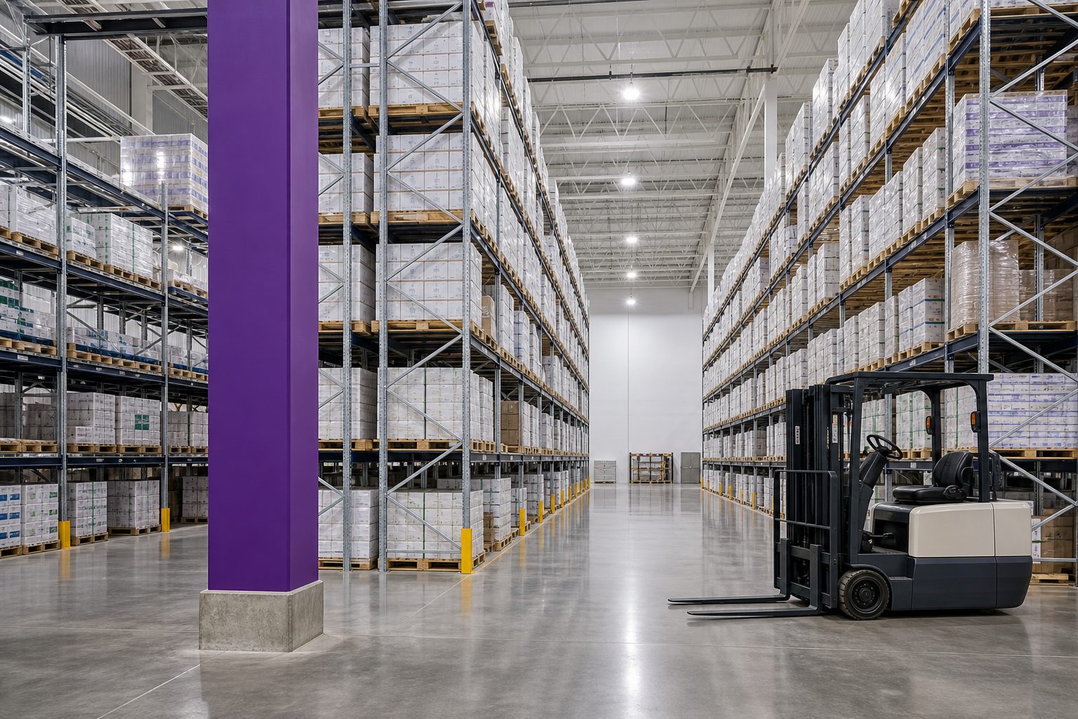
10. Flooring & Warehouse Storage
Self-leveling heavy-duty epoxy flooring (cleanroom + corridors), warehouse selective racking |
$80,000 |
$60,000 |
-$20,000 |
Seamless anti-static pharmaceutical epoxy application + structural pallet racking. |
11. Production Support & Clean Furniture
Dynamic pass boxes, SS304 material trolleys, weighing booths, nitrogen & ozone generators |
$90,000 |
$50,000 |
-$40,000 |
SS304 cleanroom support equipment consolidated into containerized factory shipment. |
12. Validation & Qualification (DQ / IQ / OQ)
Complete cGMP validation dossiers, FAT/SAT protocols, calibration certificates |
Included |
Included |
$0 |
Comprehensive documentation package prepared per WHO / EU GMP Annex 1 standards. |
13. Site Engineering Supervision & Commissioning
BTI senior commissioning engineers on-site in Angola; local staff training |
TBD |
TBD |
— |
Boarding, lodging, and local transit provided by client; engineering fees included. |
| TOTAL TURNKEY PACKAGE (USD) |
$3,260,195 |
$2,345,250 |
-$914,945 |
28.1% Capital Efficiency Optimized |